Product Description
Cylindrical gear reducer (JB/T8853-2001) and bevel gear reducer (JB/T9002-1999) is XIHU (WEST LAKE) DIS.ANG the 2 series of hard tooth surface gear products, tooth surface with low carbon alloy steel hardening, grinding, has a large carrying capacity, high transmission efficiency, reliable operation, long service life, etc. Be applicable to the metallurgical, mining, transport, cement, construction, chemical industry, textile, light industry, etc.
Working conditions shall meet the following requirements:
- highest input shaft speed is not more than 1500 RPM.
- the gear meshing linear speed is not more than 25 m/s;
- working environment temperature was minus 40 ~ 50 ºC.When working environment temperature is lower than 0 ºC, before the start of lubricating oil must be heated to 0 ºC and above. When the working environment temperature is higher than 45 ºC, heat insulation and cooling measures must be taken.
Model: ZSY280
Ratio: 7.6~67
Input speed(rpm): 750, 1000, 1500(could be changed according to customer)
Center distance(mm): 280
| Application: | Machinery |
|---|---|
| Hardness: | Hardened Tooth Surface |
| Installation: | Horizontal Type |
| Gear Shape: | Cylindrical Gear |
| Step: | Three-Step |
| Type: | Gear Reducer |
| Customization: |
Available
| Customized Request |
|---|

Can you explain the different types of gear reducers available in the market?
There are several types of gear reducers commonly used in industrial applications:
1. Spur Gear Reducers: These reducers have straight teeth and are cost-effective for applications requiring moderate torque and speed reduction. They are efficient but may produce more noise compared to other types.
2. Helical Gear Reducers: Helical gears have angled teeth, which provide smoother and quieter operation compared to spur gears. They offer higher torque capacities and are suitable for heavy-duty applications.
3. Bevel Gear Reducers: Bevel gears have conical shapes and intersect at an angle, allowing them to transmit power between non-parallel shafts. They are commonly used in applications where shafts intersect at 90 degrees.
4. Worm Gear Reducers: Worm gears consist of a worm (screw) and a mating gear (worm wheel). They offer high torque reduction and are used for applications 
What role do gear ratios play in optimizing the performance of gear reducers?
Gear ratios play a crucial role in optimizing the performance of gear reducers by determining the relationship between input and output speeds and torques. A gear ratio is the ratio of the number of teeth between two meshing gears, and it directly influences the mechanical advantage and efficiency of the gear reducer.
1. Speed and Torque Conversion: Gear ratios allow gear reducers to convert rotational speed and torque according to the needs of a specific application. By selecting appropriate gear ratios, gear reducers can either reduce speed while increasing torque (speed reduction) or increase speed while decreasing torque (speed increase).
2. Mechanical Advantage: Gear reducers leverage gear ratios to provide mechanical advantage. In speed reduction configurations, a higher gear ratio results in a greater mechanical advantage, allowing the output shaft to deliver higher torque at a lower speed. This is beneficial for applications requiring increased force or torque, such as heavy machinery or conveyor systems.
3. Efficiency: Optimal gear ratios contribute to higher efficiency in gear reducers. By distributing the load across multiple gear teeth, gear reducers with suitable gear ratios minimize stress and wear on individual gear teeth, leading to improved overall efficiency and prolonged lifespan.
4. Speed Matching: Gear ratios
How do manufacturers ensure the precision of gear tooth profiles in gear reducers?
Manufacturers employ several techniques to ensure the precision of gear tooth profiles in gear reducers, which is crucial for optimal performance and efficiency:
1. Precision Machining: Gear teeth are typically machined using advanced CNC (Computer Numerical Control) machines that can achieve high levels of accuracy and repeatability. This ensures consistent gear tooth profiles across multiple components.
2. Quality Control Measures: Rigorous quality control processes, such as dimensional inspections and profile measurements, are performed at various stages of manufacturing to verify that gear tooth profiles meet the required specifications.
3. Tooth Profile Design: Engineers use specialized software and simulation tools to design gear tooth profiles with precise involute shapes and accurate dimensions. These designs are then translated into machine instructions for manufacturing.
4. Material Selection: High-quality materials with excellent wear resistance and dimensional stability are chosen to minimize the potential for deformation or inaccuracies during machining and operation.
5. Heat Treatment: Heat treatment processes, such as carburizing and quenching, are applied to enhance the surface hardness and durability of gear teeth, reducing the risk of wear and deformation over time.
6. Tooth Grinding and Finishing: After initial machining, gear teeth often undergo precision grinding and finishing processes to achieve the desired tooth profile accuracy and surface finish.
7. Post-Processing Inspection: Gear tooth profiles are inspected again after manufacturing processes to verify that the final components meet the specified tolerances and performance criteria.
8. Computer-Aided Manufacturing (CAM): CAM software is used to generate tool paths and machining instructions, enabling precise control over tool movements and material removal during gear manufacturing.
By combining these techniques and leveraging advanced manufacturing technologies, manufacturers can achieve the necessary precision in gear tooth profiles, resulting in reliable and efficient gear reducers for various industrial applications.
enable gear reducers to match the rotational speeds of input and output shafts. This is crucial in applications where precise speed synchronization is required, such as in conveyors, robotics, and manufacturing processes.
When selecting gear ratios for a gear reducer, it’s important to consider the specific requirements of the application, including desired speed, torque, efficiency, and mechanical advantage. Properly chosen gear ratios enhance the overall performance and reliability of gear reducers in a wide range of industrial and mechanical systems.
requiring high ratios, although they can be less efficient.
5. Planetary Gear Reducers: These reducers use a system of planetary gears to achieve high torque output in a compact design. They provide excellent torque multiplication and are commonly used in robotics and automation.
6. Cycloidal Gear Reducers: Cycloidal drives use an eccentric cam to achieve speed reduction. They offer high shock load resistance and are suitable for applications with frequent starting and stopping.
7. Harmonic Drive Reducers: Harmonic drives use a flexible spline to achieve high gear reduction ratios. They provide high precision and are commonly used in applications requiring accurate positioning.
8. Hypoid Gear Reducers: Hypoid gears have helical teeth and non-intersecting shafts, making them suitable for applications with space limitations. They offer high torque and efficiency.
Each type of gear reducer has its own advantages and limitations, and the choice depends on factors such as torque requirements, speed ratios, noise levels, space constraints, and application-specific needs.


editor by CX 2023-08-17
China Professional Rx Series Foot-Mounted Single-Stage Helical Gear Unit with CZPT Shaft Reducer Gearbox manufacturer
Product Description
Product Description
Product Description
-R Series Helical gearbox
Product Features:
1.High modular design.
2.Integrated casting housing,compact dimension,high loading support, stable transmitting and low noise level.
3.Perfect oil leakage preventing makes the good sealings and can be used in wide range of industry.
4.This series is special for pug mill.
5.High efficiency and save power.
6.Save cost and low maintenance.
Design Features:
1. Compact structure, modular design
2. Single-stage, two-stage and three-stage sizes
3. Can be combined with other types of gearboxes (Such as R Series, K Series, F Series, S Series, UDL Series)
Product Parameters
1 Stage
| Models | Output Shaft Dia. | Input Shaft Dia. | Power(kW) | Ratio | Max. Torque(Nm) |
| BRX/BRXF38 | 20mm | 16mm | 0.18~1.1 | 1.62~4.43 | 20 |
| BRX/BRXF58 | 20mm | 19mm | 0.18~5.5 | 1.3~5.5 | 70 |
| BRX/BRXF68 | 25mm | 19mm | 0.18~7.5 | 1.4~6.07 | 135 |
| BRX/BRXF78 | 30mm | 24mm | 1.1~11 | 1.42~8.00 | 215 |
| BRX/BRXF88 | 40mm | 28mm | 3~22 | 1.39~8.65 | 400 |
| BRX/BRXF98 | 50mm | 38mm | 5.5~30 | 1.42~8.23 | 600 |
| BRX/BRXF108 | 60mm | 42mm | 7.5~45 | 1.44~6.63 | 830 |
| BRX/BRXF128 | 75mm | 55mm | 7.5~90 | 1.51~6.2 | 1110 |
| BRX/BRXF158 | 90mm | 70mm | 11~132 | 1.57~6.2 | 1680 |
2-3Stage
| Models | Output Shaft Dia. | Input Shaft Dia. | Power(kW) | Ratio | Max. Torque(Nm) |
| BR/BRF18 | 20mm | – | 0.18~0.75 | 3.83~74.84 | 85 |
| BR/BRF28 | 25mm | 16mm | 0.18~3 | 3.37~135.09 | 130 |
| BR/BRF38 | 25mm | 16mm | 0.18~3 | 3.41~134.82 | 200 |
| BR/BRF48 | 30mm | 19mm | 0.18~5.5 | 3.83~176.88 | 300 |
| BR/BRF58 | 35mm | 19mm | 0.18~7.5 | 4.39~186.89 | 450 |
| BR/BRF68 | 35mm | 19mm | 0.18~7.5 | 4.29~199.81 | 600 |
| BR/BRF78 | 40mm | 24mm | 0.18~11 | 5.21~195.24 | 820 |
| BR/BRF88 | 50mm | 28mm | 0.55~18.5 | 5.36~246.54 | 1550 |
| BR/BRF98 | 60mm | 38mm | 0.55~30 | 4.49~289.6 | 3000 |
| BR/BRF108 | 70mm | 42mm | 2.2~45 | 5.06~249.16 | 4300 |
| BR/BRF138 | 90mm | 55mm | 5.5~55 | 5.51~222.6 | 8000 |
| BR/BRF148 | 110mm | 55mm | 11~90 | 5.00~163.31 | 13000 |
| BR/BRF168 | 120mm | 70mm | 11~160 | 8.77~229.71 | 18000 |
Materials Data Sheet
|
Housing material |
Grey Cast iron |
|
Housing hardness |
HBS163~255 |
|
Gear material |
20CrMnTi alloy steel |
|
Surface hardness of gears |
HRC58°~62 ° |
|
Gear core hardness |
HRC33~48 |
|
Input / Output shaft material |
40Cr alloy steel |
|
Input / Output shaft hardness |
HRC32~36 |
|
Machining precision of gears |
accurate grinding, 6~5 Grade |
|
Lubricating oil |
GB L-CKC220-460, Shell Omala220-460 |
|
Heat treatment |
tempering, cementiting, quenching, normalizing, etc. |
|
Efficiency |
94%~96% (depends on the transmission stage) |
|
Noise (MAX) |
60~68dB |
|
Temp. rise (MAX) |
40°C |
|
Temp. rise (Oil)(MAX) |
50°C |
|
Vibration |
≤20µm |
|
Backlash |
≤20Arcmin |
|
Brand of bearings |
China top brand bearing, HRB/LYC/ZWZ/C&U. Or other brands requested, SKF, FAG, INA, NSK. |
|
Brand of oil seal |
NAK — ZheJiang or other brands requested |
Detailed Photos
Our process of production
Our product line
Company Profile
Company Profile
Bode was founded in 2007, which is located in HangZhou city, ZHangZhoug province. As 1 professional manufacturer and exporter, we have more than 17 years’ experience in R & D of worm reducer, gear reducer, gearbox , AC motor and relative spare parts. We have factory with advanced production and test equipment, the strong development of team and producing capacity offer our customers with high quality products. Our products widely served to various industries of Metallurgy, Chemicals, lifting, mining, Petroleum, textile, medicine, wooden etc. Main markets: China, Africa, Australia, Vietnam, Turkey, Japan, Korea, Philippines… Welcome to ask us any questions, good offer always for you for long term business.
FAQ
Q1: Are you trading company or manufacturer?
A: We are factory.
Q2: What kinds of gearbox can you produce for us?
A: Main products of our company: R, S, K, F series helical-tooth reducer, RV series worm gear reducer,H Series Parallel Shaft Helical Reduction Gear Box
Q3: Can you make as per custom drawing?
A: Yes, we offer customized service for customers.
Q4: Can we buy 1 pc of each item for quality testing?
A: Yes, we are glad to accept trial order for quality testing.
Q5: What information shall we give before placing a purchase order?
A: a) Type of the gearbox, ratio, input and output type, input flange, mounting position, and motor informationetc.
b) Housing color.
c) Purchase quantity.
d) Other special requirements.
Q6: How long is your delivery time?
A: Generally it is 5-10 days if the goods are in stock. or it is 15-20 days if the goods are not in stock.
Q7: What is your terms of payment ?
A: 30% Advance payment by T/T after signing the contract.70% before delivery
If you are interested in our product, welcome to contact with us.
Our team will do our best to meet your need 🙂
| Application: | Machinery, Marine, Agricultural Machinery |
|---|---|
| Function: | Distribution Power, Change Drive Torque, Speed Changing, Speed Reduction |
| Layout: | Coaxial |
| Hardness: | Hardened Tooth Surface |
| Installation: | Vertical Type |
| Step: | Single-Step |
| Samples: |
US$ 50/Piece
1 Piece(Min.Order) What are the considerations for choosing the appropriate lubrication for gear reducers?Choosing the appropriate lubrication for gear reducers is crucial for ensuring optimal performance, longevity, and efficiency. Several considerations should be taken into account when selecting the right lubrication: 1. Load and Torque: The magnitude of the load and torque transmitted by the gear reducer affects the lubrication’s viscosity and film strength requirements. Heavier loads may necessitate higher viscosity lubricants. 2. Operating Speed: The speed at which the gear reducer operates impacts the lubrication’s ability to maintain a consistent and protective film between gear surfaces. 3. Temperature Range: Consider the temperature range of the operating environment. Lubricants with suitable viscosity indexes are crucial to maintaining performance under varying temperature conditions. 4. Contaminant Exposure: If the gear reducer is exposed to dust, dirt, water, or other contaminants, the lubrication should have proper sealing properties and resistance to contamination. 5. Lubrication Interval: Determine the desired maintenance interval. Some lubricants require more frequent replacement, while others offer extended operational periods. 6. Compatibility with Materials: Ensure that the chosen lubricant is compatible with the materials used in the gear reducer, including gears, bearings, and seals. 7. Noise and Vibration: Some lubricants have properties that can help reduce noise and dampen vibrations, improving the overall user experience. 8. Environmental Impact: Consider environmental regulations and sustainability goals when selecting lubricants. 9. Manufacturer Recommendations: Follow the manufacturer’s recommendations and guidelines for lubrication type, viscosity grade, and maintenance intervals. 10. Monitoring and Analysis: Implement a lubrication monitoring and analysis program to assess lubricant condition and performance over time. By carefully evaluating these considerations and consulting with lubrication experts, industries can choose the most suitable lubrication for their gear reducers, ensuring reliable and efficient operation. | |
|---|

| Customization: |
Available
| Customized Request |
|---|
Function of Gear Reducers in Mechanical Systems
A gear reducer, also known as a gear reduction unit or gearbox, is a mechanical device designed to reduce the speed of an input shaft while increasing its torque output. It accomplishes this through the use of a set of interlocking gears with different sizes.
The primary function of a gear reducer in mechanical systems is to:
- Speed Reduction: The gear reduc

How do gear reducers handle shock loads and sudden changes in torque?
Gear reducers are designed to handle shock loads and sudden changes in torque through several mechanisms that enhance their durability and reliability in challenging operating conditions.
1. Robust Construction: Gear reducers are constructed using high-strength materials and precision manufacturing techniques. This ensures that the gears, bearings, and other components can withstand sudden impacts and high torque fluctuations without deformation or failure.
2. Shock-Absorbing Features: Some gear reducer designs incorporate shock-absorbing features, such as flexible couplings, elastomeric elements, or torsionally flexible gear designs. These features help dampen and dissipate the energy from sudden shocks or torque spikes, reducing the impact on the entire system.
3. Torque Limiters: In applications where shock loads are common, torque limiters may be integrated into the gear reducer. These devices automatically disengage or slip when a certain torque threshold is exceeded, preventing damage to the gears and other components.
4. Overload Protection: Gear reducers can be equipped with overload protection mechanisms, such as shear pins or torque sensors. These mechanisms detect excessive torque and disengage the drive temporarily, allowing the system to absorb the shock or adjust to the sudden torque change.
5. Proper Lubrication: Adequate lubrication is essential for managing shock loads and sudden torque changes. High-quality lubricants reduce friction and wear, helping the gear reducer withstand dynamic forces and maintain smooth operation.
6. Dynamic Load Distribution: Gear reducers distribute dynamic loads across multiple gear teeth, which helps prevent localized stress concentrations. This feature minimizes the risk of tooth breakage and gear damage when subjected to sudden changes in torque.
By incorporating these design features and mechanisms, gear reducers can effectively handle shock loads and sudden changes in torque, ensuring the longevity and reliability of various industrial and mechanical systems.
er takes the high-speed rotation of the input shaft and transmits it to the output shaft through a set of gears. The gears are configured in such a way that the output gear has a larger diameter than the input gear. As a result, the output shaft rotates at a lower speed than the input shaft, but with increased torque.
- Torque Increase: Due to the size difference between the input and output gears, the torque applied to the output shaft is greater than that of the input shaft. This torque multiplication allows the system to handle heavier loads and perform tasks requiring higher force.
Gear reducers are widely used in various industries and applications where it’s necessary to adapt the speed and torque characteristics of a power source to meet the requirements of the driven equipment. They can be found in machinery such as conveyor systems, industrial machinery, vehicles, and more.
editor by CX 2023-08-17
China factory Wpf040 2stage Straight Teeth Transmission Precison Planetary Reducer Gearbox for Servo Motor, ≤ 0.4kw with Good quality
Product Description
Product Description
| Ratio : | 3:1—-10000:1 | Backlash : | up to 8 arcmin |
| Output : | up to 65000N.m | Frame : | PF/WPF040-550 |
Output: Straight teeth Ball bearing
Single support
WPF core feature
Structural feature
Reducer output planetary frame, gear ring are using split structure design, reducer parameters are uniform and good, product processing technology is the same as high-end products, and the same high precision processing equipment manufacturing, cost-effective.
Reducer gear ring, planetary frame, input shaft are made of 40Cr high-quality structural steel, hot forging process, so as to obtain higher material density, than the use of casting box, round steel, with higher strength, rigidity, toughness.
Gear characteristics
Real hard face spur gear, gear material is 20CrMnTi high quality alloy steel, after carburizing – grinding process processing, hardness up to HRC62, compared with ordinary steel 40Cr, 38CrMnTi surface nitriding treatment of gear has higher hardness, rigidity, toughness, wear resistance. The design and analysis technology of 3DSimulation is adopted to modify the tooth shape, tooth direction and follow the trimming, respectively, in order to reduce the noise of gear meshing and increase the service life of the gear train.
Application characteristics
The product parameters are uniform and good, can bear a certain radial and axial load, low and medium precision requirements, excellent performance.
Installation Instructions
Precision planetary reducer – about installation
| Application: | Motor, Electric Cars, Machinery, Agricultural Machi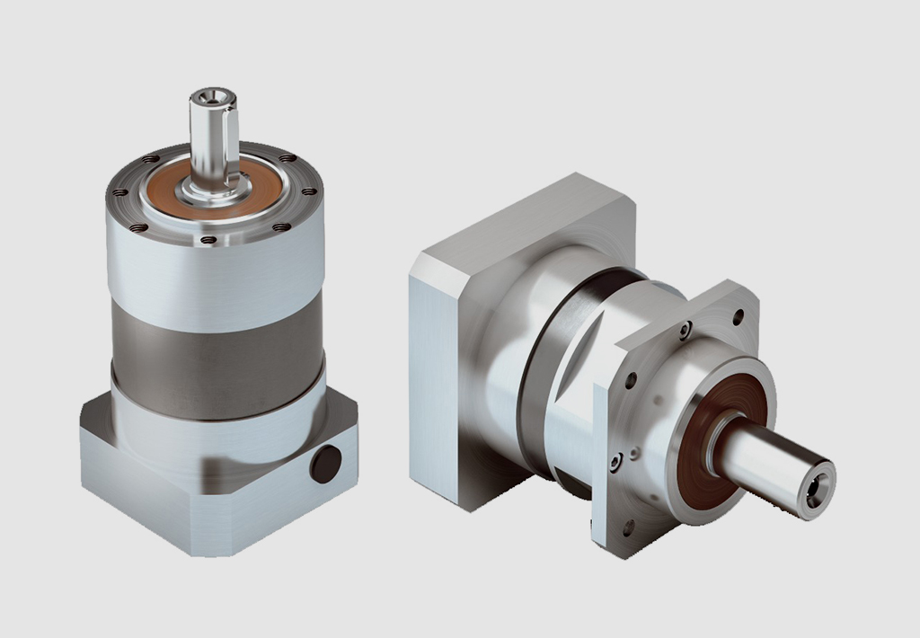
Precision of Gear Tooth Profiles in Servo GearboxesManufacturers take several measures to ensure the precision of gear tooth profiles in servo gearboxes: 1. Advanced Manufacturing Processes: Manufacturers use advanced machining techniques such as CNC (Computer Numerical Control) machining and grinding to achieve high precision in gear tooth profiles. These processes allow for accurate shaping and finishing of the gear teeth. 2. Quality Materials: High-quality materials with consistent properties are selected for manufacturing gear components. This ensures uniformity in the gear teeth and minimizes variations that could affect precision. 3. Tight Tolerances: Manufacturers set tight tolerances for gear tooth dimensions, including pitch, profile, and helix angle. This helps to maintain precise engagement between gear teeth, reducing backlash and ensuring accurate motion control. 4. Quality Control: Rigorous quality control measures are implemented at various stages of the manufacturing process. This includes inspections, measurements, and tests to verify that gear tooth profiles meet the required specifications. 5. CNC Gear Inspection: Manufacturers use CNC gear inspection machines that can measure and analyze gear tooth profiles with high accuracy. These machines generate detailed reports about tooth geometry, ensuring compliance with design specifications. 6. Computer-Aided Design (CAD) and Simulation: Manufacturers use CAD software to design gear tooth profiles with precision. Simulation tools analyze how different factors, such as material properties and manufacturing processes, affect the final gear tooth shape. 7. Profile Corrections: In some cases, manufacturers apply profile corrections to optimize gear tooth profiles. These corrections compensate for any deviations that may occur during the manufacturing process. 8. Feedback from Application: Manufacturers often collaborate closely with end-users to gather feedback on the performance of gearboxes in real-world applications. This feedback helps refine the manufacturing process and improve the precision of gear tooth profiles. The combination of advanced manufacturing techniques, strict quality control, and continuous improvement processes ensures that servo gearboxes maintain the precision required for accurate motion control in various applications. nery |
|---|---|
| Hardness: | Hardened Tooth Surface |
| Installation: | Vertical Type |
| Layout: | Coaxial |
| Gear Shape: | Cylindrical Gear |
| Step: | Double-Step |
| Samples: |
US$ 185/Piece
1 Piece(Min.Order) | |
|---|
| Customization: |
Available
| Customized Request |
|---|

Benefits of Using a Servo Gearbox for Precise Motion Control
Servo gearboxes offer several advantages when it comes to achieving precise motion control in various applications:
1. Accuracy: Servo gearboxes provide exceptional accuracy in speed and position control, making them suitable for applications that require tight tolerances and precise movements.
2. Low Backlash: These gearboxes are designed to minimize backlash, which is essential for eliminating lost motion and ensuring accurate positioning.
3. High Torque Density: Servo gearboxes offer a high torque-to-size ratio, allowing them to handle significant loads while maintaining a compact footprint.
4. Dynamic Performance: They excel in dynamic performance, enabling rapid changes in speed and direction with minimal overshoot or settling time.
5. Responsiveness: Servo gearboxes respond quickly to control signals, making them ideal for applications that require rapid adjustments and changes in direction.
6. Smooth Operation: These gearboxes provide smooth and precise movement, critical for applications like robotics, where jerky or uneven motion can lead to inaccuracies or damage.
7. Reduces Maintenance: The accuracy and durability of servo gearboxes can reduce wear and tear on other components, leading to lower maintenance requirements.
8. Improved Efficiency: Servo gearboxes offer high efficiency in power transmission, contributing to energy savings and minimizing heat generation.
9. Customization: They can be tailored to specific application needs, including factors like reduction ratios, mounting options, and feedback compatibility.
10. Versatility: Servo gearboxes find application in various industries, including robotics, CNC machining, medical equipment, and automation.
Overall, the benefits of using a servo gearbox for precise motion control make them an essential component in applications that demand accuracy, responsiveness, and reliable performance.
editor by CX 2023-08-17
China Hot selling Da120 Helical Gear 1.5kw Servo Motor Transmission Gearbox Fubao cycloidal gearbox
Product Description
Product Description
Reducer production factory For sale helical gear 1.5KW servo motor transmission gearbox
DA series precision square flange high precision reducer. Reducer bearings are CZPT brand, gear after carbonization treatment, so the accuracy and rigidity are superior! Reducer output shaft is customized size and length according to customer requirements.
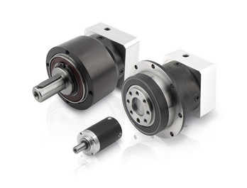
Fubao planetary gear box manufacturer, the supply of high-precision planetary reducer has the following advantages:
1, compact structure: the characteristics of large torque planetary reducer is to make full use of space, limited space design bearing and gear ratio, so that the product is smaller than the traditional reducer volume can save space.
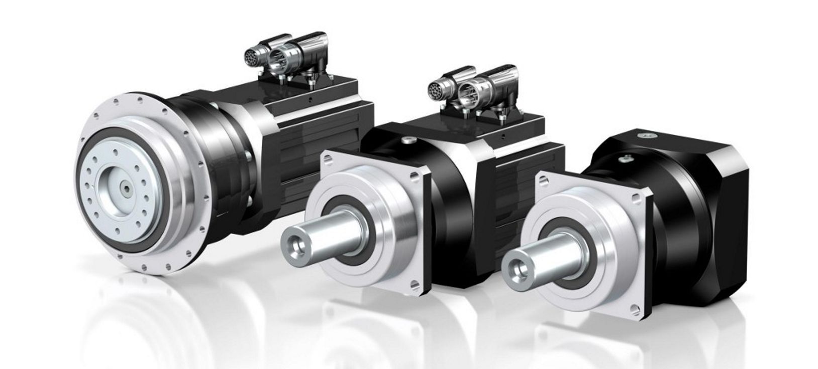
2, high efficiency: the planetary gear group will be in a completely tight meshing state when running, reducing gear collision or local meshing resulting in gear damage. The completely tight meshing characteristic makes the efficiency loss of each gear transmission only 3%. This type of transmission mode can ensure that the kinetic energy input reducer to the mechanical end of the process, still can maintain high transmission efficiency, avoid the internal gear friction, sliding, mechanical loss.
3, high axial and radial load capacity: the output shaft of Fubao technology’s high-torque planetary reducer adopts a large-span style, so that the bearing is configured at both ends of the output shaft. The design can effectively disperse the force acting on the output shaft and reduce the load of the bearing. In other words, the product strengthens the bearing and radial load capacity under the same size.
4, high strength: large torque planetary reducer gear group is very strong and stable, the thickness of the gear dispersed the load on the gear. The large span bearing group provides a stable structure, and the precision gear group allows the load to be distributed to each planetary gear under tight meshing to withstand the torque load.
5, high stability: precision processing to ensure that the product coaxial and concentric, coupled with bearing large span design, so that large torque planetary reducer with excellent stability.
Product Parameters
| DA series parameters | Model number | DA60 | DA090 | DA120 | DA150 | |
| Rated output torque | 40~60Nm | 120~340Nm | 230~340Nm | 450~650Nm | ||
| Reduction ratio | L1:3,5,7,10 L2:9,12,15,16,20,21,25,28,30,30,40,49,50,70 | |||||
| Planetary gear backlash | L1PO:≤1 P1≤3 P2≤5 L2 P0≤3 P1≤5 P2≤7 | |||||
Detailed Photos
Product Classification
Company Profile
Factory Display
Q: Speed reducer grease replacement time
A: When sealing appropriate amount of grease and running reducer, the standard replacement time is 20000 hours according to the aging condition of the grease. In addition, when the grease is stained or used in the surrounding temperature condition (above 40ºC), please check the aging and fouling of the grease, and specify the replacement time.
Q: Delivery time
A: Fubao has 2000+ production base, daily output of 1000+ units, standard models within 7 days of delivery.
Q: Reducer selection
A: Fubao provides professional product selection guidance, with higher product matching degree, higher cost performance and higher utilization rate.
Q: Application range of reducer
A: Fubao has a professional research and development team, complete category design, can match any stepping motor, servo motor, more accurate matching.
|
Shipping Cost:
Estimated freight per unit. |
To be negotiated |
|---|
| Application: | Motor, Machinery, Agricultural Machinery, Mechanical Equipment |
|---|---|
| Function: | Distribution Power, Change Drive Torque, Speed Changing, Speed Reduction, Reduce Motor Speed |
| Layout: | Cycloidal |
| Customization: |
Available
| Customized Request |
|---|

Servo Gearbox: Function in Motion Control Systems
A servo gearbox is a specialized type of gearbox designed to work in conjunction with servo motors to achieve precise motion control in various applications. It functions as follows:
Motion Synchronization: A servo gearbox is used to synchronize the motion of a servo motor with the intended motion of a mechanical system. It ensures that the motor’s rotational output is accurately transmitted to the driven component.
Speed and Position Control: Servo gearboxes enable precise control over speed and position by converting the high-speed, low-torque output of a servo motor into a lower-speed, higher-torque output suitable for the specific application.
Reduction Ratio: The servo gearbox incorporates reduction stages to achieve the desired reduction ratio. This reduction allows the motor to provide higher torque while maintaining accurate speed control.
Backlash Minimization: High-precision servo gearboxes are designed to minimize backlash, which is the lost motion between input and output shafts. This is critical for accurate and responsive motion control.
High Efficiency: Servo gearboxes are designed for high efficiency to ensure that the majority of input power is effectively transferred to the output, reducing energy consumption.
Dynamic Response: Servo gearboxes enhance the dynamic response of motion control systems. They allow the servo motor to quickly start, stop, and change directions with minimal overshooting or oscillations.
Positioning Accuracy: By accurately converting the motor’s rotation into precise linear or angular movement, servo gearboxes ensure high positioning accuracy required in applications such as robotics, CNC machines, and automation systems.
Load Distribution: Servo gearboxes distribute the load evenly across gear teeth, enhancing the gearbox’s durability and minimizing wear.
Customization: Servo gearboxes are available in various sizes, reduction ratios, and configurations to suit different application requirements.
Overall, a servo gearbox is an integral component in motion control systems, allowing precise and efficient control over motion, speed, and position for a wide range of industrial applications.
editor by CX 2023-08-17
China Professional Nmrv Series Worm Gear Reducer with Output and Input Flanges wholesaler
Product Description
Product Description
RV series Characteristics
- RV – Sizes:–150
- Input Options: with input shaft, With Square flange,With Input Flange
- Input Power 0.06 to 11 kW
- RV-Size from 030 to 105 in die-cast aluminium alloy budy and over 110 in cast iron
- Ratios between 5 and 100
- Max torque 1550 N.m and admissible output radial loads max 8771 N
- Aluminium units are supplied complete with synthetic oil and allow for universal mounting positions, with no need to modify lubricant quantity
- Worm wheel: Copper (KK Cu).
- Loading capacity in accordance with: ISO 9001:2015/GB/T 19001-2016
- Size 030 and over are painted with RAL 5571 blue
- Worm gear reducers are available with diffferent combinations: NMRV+NMRV, NMRVpower+NMRV, JWB+NMRV
- NMRV, NRV+VS,NMRV+AS,NMRV+VS,NMRV+F
- Options: torque arm, output flange, viton oil seals, low/high temperature oil, filling/drain/breather/level plug,Small gap
| WORM GEARBOX | |||||
| SNW SERIES | Output Speed Range: | ||||
| Type | Old Type | Output Torque | Output Shaft Dia. | 14rpm-280rpm | |
| SNW030 | RV030 | 21N.m | φ14 | Applicable Motor Power: | |
| SNW040 | RV040 | 45N.m | φ19 | 0.06kW-11kW | |
| SNW050 | RV050 | 84N.m | φ25 | Input Options1: | |
| SNW063 | RV063 | 160N.m | φ25 | With Inline AC Motor | |
| SNW075 | RV075 | 230N.m | φ28 | Input Options2: | |
| SNW090 | RV090 | 410N.m | φ35 | With Square flange | |
| SNW105 | RV105 | 630N.m | φ42 | Input Options3: | |
| SNW110 | RV110 | 725N.m | φ42 | With Input Shaft | |
| SNW130 | RV130 | 1050N.m | φ45 | Input Options4: | |
| SNW150 | RV150 | 1550N.m | φ50 | With Input Flange |
Photos of the factory area
ZHangZhoug Boqiang Transmission Co., Ltd. was established in 2002 and is a high-tech enterprise that integrates design, development, manufacturing, and operation, producing and selling reduction motors and power transmission equipment. The company is located in Oubei Town, HangZhoua County, at the forefront of national reform and opening up, known as the “Little Xihu (West Lake) Dis.” of HangZhou. Close to National Highway 104 and east to HangZhou International Airport and Xihu (West Lake) Dis. International Container Terminal; South to HangZhou Railway Station and Passenger Transport Center; There are also many national tourist attractions such as Yandang Mountain and Xihu (West Lake) Dis. River. With convenient transportation and unique geographical location, it is highly welcomed by domestic and foreign users.
Our company produces 12 series of helical gear reducers for various purposes, including shaft mounted helical gear reducers, helical bevel gear reducers, helical worm gear reducers, spiral bevel gear steering boxes, worm gear reducers, continuously variable transmissions, spiral elevators, and large gearboxes. The power coverage is 0.12-2000kw, with a reduction ratio of 1.25-30000. Various combinations, deformations, and specialized products can meet most industrial requirements. The R, K, F, and S series reducers adopt the modular design principle of unit structure, greatly reducing the types of components and inventory, and greatly shortening the delivery cycle. The components have strong universality and low maintenance costs.
Boqiang has a leading position in China in terms of technology level and product market share. The products are widely used in various fields such as metallurgy, light industry, packaging, medicine, petroleum, chemical industry, lifting and transportation, three-dimensional parking, printing and dyeing, elevators, wind power, etc. Boqiang Company has excellent performance. The transmission technology experts from the headquarters and numerous application engineers and after-sales service technicians from various regional offices provide you with rapid and comprehensive technical consultation and comprehensive services.
Looking back at the past and looking CZPT to the future, Boqiang has always been on the way forward, constantly improving and surpassing itself with high-quality products and comprehensive services, and winning the favor of the market and customers. We are willing to work together with people of insight from all walks of life to create a more brilliant tomorrow.
Processing equipment
Testing equipment and quality control
Quality:Insist on Improvement,Strive for CZPT With the development of equipment manufacturing indurstry,customer never satirsfy with the current quality of our products,on the contrary,wcreate the value of quality.
Quality policy:to enhance the overall level in the field of power transmission
Quality View:Continuous Improvement , pursuit of excellence
Quality Philosophy:Quality creates value
Product matching
Packaging And Transportation
FAQ
Q1: Are you trading company or manufacturer?
A: We are factory.
Q2: What kinds of gearbox can you produce for us?
A: Main products of our company: R, S, K, F series helical-tooth reducer, RV series worm gear reducer,H Series Parallel Shaft Helical Reduction Gear Box
Q3: Can you make as per custom drawing?
A: Yes, we offer customized service for customers.
Q4: Can we buy 1 pc of each item for quality testing?
A: Yes, we are glad to accept trial order for quality testing.
Q5: What information shall we give before placing a purchase order?
A: a) Type of the gearbox, ratio, input and output type, input flange, mounting position, and motor informationetc.
b) Housing color.
c) Purchase quantity.
d) Other special requirements.
Q6: How long is your delivery time?
A: Generally it is 5-10 days if the goods are in stock. or it is 15-20 days if the goods are not in stock.
Q7: What is your terms of payment ?
A: 30% Advance payment by T/T after signing the contract.70% before delivery
| Warranty: | a Year |
|---|---|
| Hardness: | Hardened Tooth Surface |
| Layout: | Parallel |
| Step: | Double-Step |
| Installation: | Horizontal Type |
| Function: | Distribution Power, Change Drive Torque, Change Dr |
| Customization: |
Available
| Customized Request |
|---|
What role do gear ratios play in optimizing the performance of gear reducers?
Gear ratios play a crucial role in optimizing the performance of gear reducers by determining the relationship between input and output speeds and torques. A gear ratio is the ratio of the number of teeth between two meshing gears, and it directly influences the mechanical advantage and efficiency of the gear reducer.
1. Speed and Torque Conversion: Gear ratios allow gear reducers to convert rotational speed and torque according to the needs of a specific application. By selecting appropriate gear ratios, gear reducers can either reduce speed while increasing torque (speed reduction) or increase speed while decreasing torque (speed increase).
2. Mechanical Advantage: Gear reducers leverage gear ratios to provide mechanical advantage. In speed reduction configurations, a higher gear ratio results in a greater mechanical advantage, allowing the output shaft to deliver higher torque at a lower speed. This is beneficial for applications requiring increased force or torque, such as heavy machinery or conveyor systems.
3. Efficiency: Optimal gear ratios contribute to higher efficiency in gear reducers. By distributing the load across multiple gear teeth, gear reducers with suitable gear ratios minimize stress and wear on individual gear teeth, leading to improved overall efficiency and prolonged lifespan.
4. Speed Matching: Gear ratios enable gear reducers to match the rotational speeds of input and output shafts. This is crucial in applications where precise speed synchronization is required, such as in conveyors, robotics, and manufacturing processes.
When selecting gear ratios for a gear reducer, it’s important to consider the specific requirements of the application, including desired speed, torque, efficiency, and mechanical advantage. Properly chosen gear ratios enhance the overall performance and reliability of gear reducers in a wide range of industrial and mechanical systems.

Are there variations in gear reducer designs for specific tasks and applications?
Yes, gear reducer designs vary widely to suit specific tasks and applications across various industries. Manufacturers offer a range of gear reducer types and configurations to accommodate different requirements, including:
- Helical Gear Reducers: These are versatile and provide smooth and efficient torque transmission. They are commonly used in applications requiring high precision and moderate speed reduction, such as conveyors, mixers, and agitators.
- Bevel Gear Reducers: These are ideal for transmitting power between intersecting shafts.

How do gear reducers enhance the efficiency of conveyor systems and robotics?
Gear reducers play a significant role in improving the efficiency of both conveyor systems and robotics by optimizing speed, torque, and control. Here’s how they contribute:
Conveyor Systems:
In conveyor systems, gear reducers enhance efficiency in the following ways:
- Speed Control: Gear reducers allow precise control over the rotational speed of conveyor belts, ensuring that materials are transported at the desired speed for efficient production processes.
- Torque Adjustment: By adjusting gear ratios, gear reducers provide the necessary torque to handle varying loads and prevent overloading, minimizing energy wastage.
- Reverse Operation: Gear reducers enable smooth bidirectional movement of conveyor belts, facilitating tasks such as loading, unloading, and distribution without the need for additional components.
- Synchronization: Gear reducers ensure synchronized movement of multiple conveyor belts in complex systems, optimizing material flow and minimizing jams or bottlenecks.
Robotics:
In robotics, gear reducers enhance efficiency through the following means:
- Precision Movement: Gear reducers provide precise control over the movement of robot joints and arms, enabling accurate positioning and manipulation of objects.
- Reduced Inertia: Gear reducers help reduce the inertia experienced by robotic components, allowing for quicker and more responsive movements while conserving energy.
- Compact Design: Gear reducers offer a compact and lightweight solution for achieving various motion profiles in robotic systems, allowing for efficient use of space and resources.
- Torque Amplification: By amplifying torque from the motor, gear reducers enable robots to handle heavier loads and perform tasks that require greater force, enhancing their overall capabilities.
By providing precise speed control, torque adjustment, and reliable motion transmission, gear reducers optimize the performance of conveyor systems and robotics, leading to improved efficiency, reduced energy consumption, and enhanced operational capabilities.
They are often used in heavy machinery, printing presses, and automotive applications.
- Worm Gear Reducers: These provide compact solutions and are suitable for applications with higher speed reduction requirements, such as conveyor systems, winches, and elevators.
- Planetary Gear Reducers: These offer high torque density and are used in applications demanding precise control, such as robotics, aerospace, and heavy-duty machinery.
- Parallel Shaft Gear Reducers: Commonly used in industrial machinery, these reducers are designed for high torque and reliability.
- Right-Angle Gear Reducers: These are used when space limitations require a change in shaft direction, commonly found in packaging equipment and conveyors.
Each type of gear reducer has unique features and benefits that make it suitable for specific tasks. Manufacturers often provide customization options to tailor gear reducers to the precise requirements of an application, including gear ratios, mounting options, and input/output configurations.
Therefore, the variation in gear reducer designs allows industries to select the most appropriate type based on factors such as torque, speed, space constraints, precision, and environmental conditions.
editor by CX 2023-08-16
China Best Sales Rx Series Foot-Mounted Single-Stage Helical Gear Unit with CZPT Shaft Reducer Gearbox supplier
Product Description
Product Description
Product Description
-R Series Helical gearbox
Product Features:
1.High modular design.
2.Integrated casting housing,compact dimension,high loading support, stable transmitting and low noise level.
3.Perfect oil leakage preventing makes the good sealings and can be used in wide range of industry.
4.This series is special for pug mill.
5.High efficiency and save power.
6.Save cost and low maintenance.
Design Features:
1. Compact structure, modular design
2. Single-stage, two-stage and three-stage sizes
3. Can be combined with other types of gearboxes (Such as R Series, K Series, F Series, S Series, UDL Series)
Product Parameters
1 Stage
| Models | Output Shaft Dia. | Input Shaft Dia. | Power(kW) | Ratio | Max. Torque(Nm) |
| BRX/BRXF38 | 20mm | 16mm | 0.18~1.1 | 1.62~4.43 | 20 |
| BRX/BRXF58 | 20mm | 19mm | 0.18~5.5 | 1.3~5.5 | 70 |
| BRX/BRXF68 | 25mm | 19mm | 0.18~7.5 | 1.4~6.07 | 135 |
| BRX/BRXF78 | 30mm | 24mm | 1.1~11 | 1.42~8.00 | 215 |
| BRX/BRXF88 | 40mm | 28mm | 3~22 | 1.39~8.65 | 400 |
| BRX/BRXF98 | 50mm | 38mm | 5.5~30 | 1.42~8.23 | 600 |
| BRX/BRXF108 | 60mm | 42mm | 7.5~45 | 1.44~6.63 | 830 |
| BRX/BRXF128 | 75mm | 55mm | 7.5~90 | 1.51~6.2 | 1110 |
| BRX/BRXF158 | 90mm | 70mm | 11~132 | 1.57~6.2 | 1680 |
2-3Stage
| Models | Output Shaft Dia. | Input Shaft Dia. | Power(kW) | Ratio | Max. Torque(Nm) |
| BR/BRF18 | 20mm | – | 0.18~0.75 | 3.83~74.84 | 85 |
| BR/BRF28 | 25mm | 16mm | 0.18~3 | 3.37~135.09 | 130 |
| BR/BRF38 | 25mm | 16mm | 0.18~3 | 3.41~134.82 | 200 |
| BR/BRF48 | 30mm | 19mm | 0.18~5.5 | 3.83~176.88 | 300 |
| BR/BRF58 | 35mm | 19mm | 0.18~7.5 | 4.39~186.89 | 450 |
| BR/BRF68 | 35mm | 19mm | 0.18~7.5 | 4.29~199.81 | 600 |
| BR/BRF78 | 40mm | 24mm | 0.18~11 | 5.21~195.24 | 820 |
| BR/BRF88 | 50mm | 28mm | 0.55~18.5 | 5.36~246.54 | 1550 |
| BR/BRF98 | 60mm | 38mm | 0.55~30 | 4.49~289.6 | 3000 |
| BR/BRF108 | 70mm | 42mm | 2.2~45 | 5.06~249.16 | 4300 |
| BR/BRF138 | 90mm | 55mm | 5.5~55 | 5.51~222.6 | 8000 |
| BR/BRF148 | 110mm | 55mm | 11~90 | 5.00~163.31 | 13000 |
| BR/BRF168 | 120mm | 70mm | 11~160 | 8.77~229.71 | 18000 |
Materials Data Sheet
|
Housing material |
Grey Cast iron |
|
Housing hardness |
HBS163~255 |
|
Gear material |
20CrMnTi alloy steel |
|
Surface hardness of gears |
HRC58°~62 ° |
|
Gear core hardness |
HRC33~48 |
|
Input / Output shaft material |
40Cr alloy steel |
|
Input / Output shaft hardness |
HRC32~36 |
|
Machining precision of gears |
accurate grinding, 6~5 Grade |
|
Lubricating oil |
GB L-CKC220-460, Shell Omala220-460 |
|
Heat treatment |
tempering, cementiting, quenching, normalizing, etc. |
|
Efficiency |
94%~96% (depends on the transmission stage) |
|
Noise (MAX) |
60~68dB |
|
Temp. rise (MAX) |
40°C |
|
Temp. rise (Oil)(MAX) |
50°C |
|
Vibration |
≤20µm |
|
Backlash |
≤20Arcmin |
|
Brand of bearings |
China top brand bearing, HRB/LYC/ZWZ/C&U. Or other brands requested, SKF, FAG, INA, NSK. |
|
Brand of oil seal |
NAK — ZheJiang or other brands requested |
Detailed Photos
Our process of production
Our product line
Company Profile
Company Profile
Bode was founded in 2007, which is located in HangZhou city, ZHangZhoug province. As 1 professional manufacturer and exporter, we have more than 17 years’ experience in R & D of worm reducer, gear reducer, gearbox , AC motor and relative spare parts. We have factory with advanced production and test equipment, the strong development of team and producing capacity offer our customers with high quality products. Our products widely served to various industries of Metallurgy, Chemicals, lifting, mining, Petroleum, textile, medicine, wooden etc. Main markets: China, Africa, Australia, Vietnam, Turkey, Japan, Korea, Philippines… Welcome to ask us any questions, good offer always for you for long term business.
FAQ
Q1: Are you trading company or manufacturer?
A: We are factory.
Q2: What kinds of gearbox can you produce for us?
A: Main products of our company: R, S, K, F series helical-tooth reducer, RV series worm gear reducer,H Series Parallel Shaft Helical Reduction Gear Box
Q3: Can you make as per custom drawing?
A: Yes, we offer customized service for customers.
Q4: Can we buy 1 pc of each item for quality testing?
A: Yes, we are glad to accept trial order for quality testing.
Q5: What information shall we give before placing a purchase order?
A: a) Type of the gearbox, ratio, input and output type, input flange, mounting position, and motor informationetc.
b) Housing color.
c) Purchase quantity.
d) Other special requirements.
Q6: How long is your delivery time?
A: Generally it is 5-10 days if the goods are in stock. or it is 15-20 days if the goods are not in stock.
Q7: What is your terms of payment ?
A: 30% Advance payment by T/T after signing the contract.70% before delivery
If you are interested in our product, welcome to contact with us.
Our team will do our best to meet your need 🙂
| Application: | Machinery, Marine, Agricultural Machinery |
|---|---|
| Function: | Distribution Power, Change Drive Torque, Speed Changing, Speed Reduction |
| Layout: | Coaxial |
| Hardness: | Hardened Tooth Surface |
| Installation: | Vertical Type |
| Step: | Single-Step |
| Samples: |
US$ 50/Piece
1 Piece(Min.Order) | What factors should be considered when selecting the right gear reducer?Choosing the appropriate gear reducer involves considering several crucial factors to ensure optimal performance and efficiency for your specific application:
By carefully assessing these factors and consulting with gear reducer manufacturers, engineers and industry professionals can make informed decisions to select the right gear reducer for their specific application, optimizing performance, longevity, and cost-effectiveness. |
|---|

| Customization: |
Available
| Customized Request How do manufacturers ensure the precision of gear tooth profiles in gear reducers?Manufacturers employ several techniques to ensure the precision of gear tooth profiles in gear reducers, which is crucial for optimal performance and efficiency: 1. Precision Machining: Gear teeth are typically machined using advanced CNC (Computer Numerical Control) machines that can achieve high levels of accuracy and repeatability. This ensures consistent gear tooth profiles across multiple components. 2. Quality Control Measures: Rigorous quality control processes, such as dimensional inspections and profile measurements, are performed at various stages of manufacturing to verify that gear tooth profiles meet the required specifications. 3. Tooth Profile Design: Engineers use specialized software and simulation tools to design gear tooth profiles with precise involute shapes and accurate dimensions. These designs are then translated into machine instructions for manufacturing. 4. Material Selection: High-quality materials with excellent wear resistance and dimensional stability are chosen to minimize the potential for deformation or inaccuracies during machining and operation. 5. Heat Treatment: Heat treatment processes, such as carburizing and quenching, are applied to enhance the surface hardness and durability of gear teeth, reducing the risk of wear and deformation over time. 6. Tooth Grinding and Finishing: After initial machining, gear teeth often undergo precision grinding and finishing processes to achieve the desired tooth profile accuracy and surface finish. 7. Post-Processing Inspection: Gear tooth profiles are inspected again after manufacturing processes to verify that the final components meet the specified tolerances and performance criteria. 8. Computer-Aided Manufacturing (CAM): CAM software is used to generate tool paths and machining instructions, enabling precise control over tool movements and material removal during gear manufacturing. By combining these techniques and leveraging advanced manufacturing technologies, manufacturers can achieve the necessary precision in gear tooth profiles, resulting in reliable and efficient gear reducers for various industrial applications. |
|---|

How do gear reducers contribute to speed reduction and torque increase?
Gear reducers play a crucial role in mechanical systems by achieving speed reduction and torque increase through the principle of gear ratios. Here’s how they work:
Gear reducers consist of multiple gears with different sizes, known as gear pairs. These gears are meshed together, and their teeth interlock to transmit motion and power. The gear ratio is determined by the ratio of the number of teeth on the input gear (driver) to the number of teeth on the output gear (driven).
Speed Reduction: When a larger gear (output gear) is driven by a smaller gear (input gear), the output gear rotates at a slower speed than the input gear. This reduction in speed is proportional to the gear ratio. As a result, gear reducers are used to slow down the rotational speed of the output shaft compared to the input shaft.
Torque Increase: The interlocking teeth of gears create a mechanical advantage that allows gear reducers to increase torque output. When the input gear applies a force (torque) to the teeth, it is transmitted to the output gear with greater force due to the leverage provided by the larger diameter of the output gear. The torque increase is inversely proportional to the gear ratio and is essential for applications requiring high torque at lower speeds.
By selecting appropriate gear ratios and arranging gear pairs, gear reducers can achieve various speed reduction and torque multiplication factors, making them essential components in machinery and equipment where precise control of speed and torque is necessary.
editor by CX 2023-08-16
China factory RV Square Flange Worm Gear Unit Gearbox for Servo Motor planetary gearbox
Product Description
Product Description
Main Materials:
1)housing:aluminium alloy ADC12(size 571-090); die cast iron HT200(size 110-150);
2)Worm:20Cr, ZI Involute profile; carbonize&quencher heat treatment make gear surface hardness up to 56-62 HRC; After precision grinding, carburization layer’s thickness between 0.3-0.5mm.
3)Worm Wheel:wearable stannum alloy CuSn10-1
Detailed Photos
Combination Options:
Input:with input shaft, With square flange,With IEC standard input flange
Output:with torque arm, output flange, single output shaft, double output shaft, plastic cover
Worm reducers are available with diffferent combinations: NMRV+NMRV, NMRV+NRV, NMRV+PC, NMRV+UDL, NMRV+MOTORS
Exploded View:
Product Parameters
| Old Model |
New Model | Ratio | Center Distance | Power | Input Dia. | Output Dia. | Output Torque | Weight |
| RV571 | 7.5~100 | 25mm | 0.06KW~0.12KW | Φ9 | Φ11 | 21N.m | 0.7kgs | |
| RV030 | RW030 | 7.5~100 | 30mm | 0.06KW~0.25KW | Φ9(Φ11) | Φ14 | 45N.m | 1.2kgs |
| RV040 | RW040 | 7.5~100 | 40mm | 0.09KW~0.55KW | Φ9(Φ11,Φ14) | Φ18(Φ19) | 84N.m | 2.3kgs |
| RV050 | RW050 | 7.5~100 | 50mm | 0.12KW~1.5KW | Φ11(Φ14,Φ19) | Φ25(Φ24) | 160N.m | 3.5kgs |
| RV063 | RW063 | 7.5~100 | 63mm | 0.18KW~2.2KW | Φ14(Φ19,Φ24) | Φ25(Φ28) | 230N.m | 6.2kgs |
| RV075 | RW075 | 7.5~100 | 75mm | 0.25KW~4.0KW | Φ14(Φ19,Φ24,Φ28) | Φ28(Φ35) | 410N.m | 9.0kgs |
| RV090 | RW090 | 7.5~100 | 90mm | 0.37KW~4.0KW | Φ19(Φ24,Φ28) | Φ35(Φ38) | 725N.m | 13.0kgs |
| RV110 | RW110 | 7.5~100 | 110mm | 0.55KW~7.5KW | Φ19(Φ24,Φ28,Φ38) | Φ42 | 1050N.m | 35.0kgs |
| RV130 | RW130 | 7.5~100 | 130mm | 0.75KW~7.5KW | Φ24(Φ28,Φ38) | Φ45 | 1550N.m | 48.0kgs |
| RV150 | RW150 | 7.5~100 | 150mm | 2.2KW~15KW | Φ28(Φ38,Φ42) | Φ50 | 84.0kgs |
GMRV Outline Dimension:
| GMRV | A | B | C | C1 | D(H8) | E(h8) | F | G | G1 | H | H1 | I | M | N | O | P | Q | R | S | T | BL | β | b | t | V |
| 030 | 80 | 97 | 54 | 44 | 14 | 55 | 32 | 56 | 63 | 65 | 29 | 55 | 40 | 57 | 30 | 75 | 44 | 6.5 | 21 | 5.5 | M6*10(n=4) | 0° | 5 | 16.3 | 27 |
| 040 | 100 | 121.5 | 70 | 60 | 18(19) | 60 | 43 | 71 | 78 | 75 | 36.5 | 70 | 50 | 71.5 | 40 | 87 | 55 | 6.5 | 26 | 6.5 | M6*10(n=4) | 45° | 6 | 20.8(21.8) | 35 |
| 050 | 120 | 144 | 80 | 70 | 25(24) | 70 | 49 | 85 | 92 | 85 | 43.5 | 80 | 60 | 84 | 50 | 100 | 64 | 8.5 | 30 | 7 | M8*12(n=4) | 45° | 8 | 28.3(27.3) | 40 |
| 063 | 144 | 174 | 100 | 85 | 25(28) | 80 | 67 | 103 | 112 | 95 | 53 | 95 | 72 | 102 | 63 | 110 | 80 | 8.5 | 36 | 8 | M8*12(n=8) | 45° | 8 | 28.3(31.3) | 50 |
| 075 | 172 | 205 | 120 | 90 | 28(35) | 95 | 72 | 112 | 120 | 115 | 57 | 112.5 | 86 | 119 | 75 | 140 | 93 | 11 | 40 | 10 | M8*14(n=8) | 45° | 8(10) | 31.3(38.3) | 60 |
| 090 | 206 | 238 | 140 | 100 | 35(38) | 110 | 74 | 130 | 140 | 130 | 67 | 129.5 | 103 | 135 | 90 | 160 | 102 | 13 | 45 | 11 | M10*16(n=8) | 45° | 10 | 38.3(41.3) | 70 |
| 110 | 255 | 295 | 170 | 115 | 42 | 130 | – | 144 | 155 | 165 | 74 | 160 | 127.5 | 167.5 | 110 | 200 | 125 | 14 | 50 | 14 | M10*18(n=8) | 45° | 12 | 45.3 | 85 |
| 130 | 293 | 335 | 200 | 120 | 45 | 180 | – | 155 | 170 | 215 | 81 | 179 | 146.5 | 187.5 | 130 | 250 | 140 | 16 | 60 | 15 | M12*20(n=8) | 45° | 14 | 48.8 | 100 |
| 150 | 340 | 400 | 240 | 145 | 50 | 180 | – | 185 | 200 | 215 | 96 | 210 | 170 | 230 | 150 | 250 | 180 | 18 | 72.5 | 18 | M12*22(n=8) | 45° | 14 | 53.8 | 120 |
Company Profile
About CZPT Transmission:
We are a professional reducer manufacturer located in HangZhou, ZHangZhoug province.
Our leading products is full range of RV571-150 worm reducers , also supplied GKM hypoid helical gearbox, GRC inline helical gearbox, PC units, UDL Variators and AC Motors, G3 helical gear motor.
Products are widely used for applications such as: foodstuffs, ceramics, packing, chemicals, pharmacy, plastics, paper-making, construction machinery, metallurgic mine, environmental protection engineering, and all kinds of automatic lines, and assembly lines.
With fast delivery, superior after-sales service, advanced producing facility, our products sell well both at home and abroad. We have exported our reducers to Southeast Asia, Eastern Europe and Middle East and so on.Our aim is to develop and innovate on basis of high quality, and create a good reputation for reducers.
Packing information:Plastic Bags+Cartons+Wooden Cases , or on request
We participate Germany Hannver Exhibition-ZheJiang PTC Fair-Turkey Win Eurasia
Logistics
After Sales Service
1.Maintenance Time and Warranty:Within 1 year after receiving goods.
2.Other Service: Including modeling selection guide, installation guide, and problem resolution guide, etc.
FAQ
1.Q:Can you make as per customer drawing?
A: Yes, we offer customized service for customers accordingly. We can use customer’s nameplate for gearboxes.
2.Q:What is your terms of payment ?
A: 30% deposit before production,balance T/T before delivery.
3.Q:Are you a trading company or manufacturer?
A:We are a manufacurer with advanced equipment and experienced workers.
4.Q:What’s your production capacity?
A:8000-9000 PCS/MONTH
5.Q:Free sample is available or not?
A:Yes, we can supply free sample if customer agree to pay for the courier cost
6.Q:Do you have any certificate?
A:Yes, we have CE certificate and SGS certificate report.
Contact information:
Ms Lingel Pan
For any questions just feel free ton contact me. Many thanks for your kind attention to our company!
| Application: | Motor, Machinery, Marine, Agricultural Machinery, Industry |
|---|---|
| Function: | Distribution Power, Change Drive Torque, Change Drive Direction, Speed Changing, Speed Reduction |
| Layout: | Right Angle |
| Hardness: | Hardened Tooth Surface |
| Installation: | Horizontal Type |
| Step: | Double-Step |
| Samples: |
US$ 10/Piece
1 Piece(Min.Order) | |
|---|
| Customization: |
Available
| Customized Request |
|---|
Servo Gearboxes vs. Standard Gearboxes in Industrial Applications
Servo gearboxes and standard gearboxes serve distinct roles in industrial applications. Here’s how they differ:
Precision Control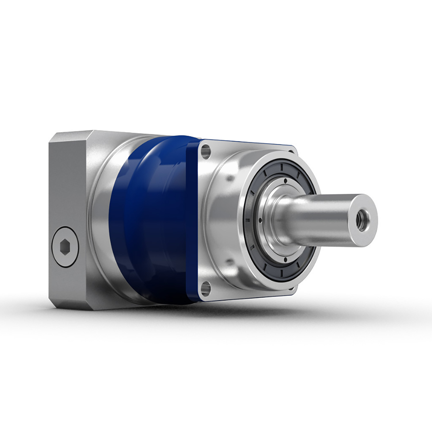
Customization of Servo Gearboxes for Specific Industrial Needs
Servo gearboxes can indeed be customized to meet specific industrial requirements. Manufacturers offer customization options to ensure that the servo gearboxes are optimized for the intended applications:
1. Gear Ratio Selection: Depending on the desired speed and torque output, manufacturers can provide various gear ratios to achieve the required motion characteristics.
2. Torque and Speed Ratings: Servo gearboxes can be tailored to handle different torque and speed demands, ensuring that they can efficiently operate within the specified parameters of the application.
3. Mounting Configurations: Manufacturers offer various mounting options, such as flange mounts or shaft mounts, to suit the mechanical layout of the machinery.
4. Output Shaft Configuration: Custom output shaft configurations, such as different diameters or keyway options, can be provided based on the integration requirements.
5. Environmental Considerations: For applications with specific environmental conditions, such as high humidity or extreme temperatures, servo gearboxes can be designed with protective features or special coatings.
6. Lubrication and Sealing: Custom lubrication options and sealing mechanisms can be incorporated to ensure optimal performance and longevity in the given environment.
7. Feedback Devices: Some applications may require specific feedback devices, such as encoders or resolvers, for precise motion control. Manufacturers can integrate these devices into the gearbox design.
8. Noise Reduction: Customized designs can include features that reduce noise and vibration, which is crucial in noise-sensitive applications.
9. Compact Designs: Manufacturers can work on compact designs to accommodate space constraints in the machinery.
10. Integration with Motors: Customized servo gearboxes can be designed to seamlessly integrate with specific types of motors, ensuring efficient power transmission.
By offering customization option
Handling Sudden Changes in Direction and Speed with Servo Gearboxes
Servo gearboxes are designed to handle sudden changes in direction and speed effectively, ensuring precise motion control even during dynamic operations. They employ several mechanisms to address these challenges:
1. Acceleration and Deceleration Profiles: Servo systems can be programmed with specific acceleration and deceleration profiles. This means that when a sudden change in speed or direction is commanded, the system can ramp up or down the speed smoothly, reducing the impact of sudden changes on the mechanical components.
2. Closed-Loop Control: Servo systems operate in a closed-loop configuration, where feedback sensors continuously monitor the actual position and speed of the system. When a sudden change is commanded, the controller can make real-time adjustments to ensure the system reaches the desired position accurately and smoothly.
3. Torque Control: Servo gearboxes are designed to provide high torque output even at low speeds. This is crucial for handling sudden changes in direction and speed, as the gearbox can deliver the required torque to quickly accelerate or decelerate the load.
4. Dynamic Response: Servo systems have fast dynamic response capabilities, which means they can quickly adapt to changes in input commands. This responsiveness allows the system to handle sudden changes in direction and speed without sacrificing accuracy or stability.
5. Electronic Damping: Some advanced servo systems incorporate electronic damping mechanisms that can be adjusted based on the application’s requirements. This feature helps dampen vibrations and oscillations that may occur during sudden changes in motion.
6. Overcurrent and Overvoltage Protection: Servo systems are equipped with protection mechanisms that detect excessive currents or voltages. If a sudden change in direction or speed causes abnormal loads or voltages, the system can take corrective actions to prevent damage.
Overall, servo gearboxes excel in handling sudden changes in direction and speed by leveraging their closed-loop control, high torque output, and fast dynamic response capabilities. These features allow them to provide accurate and reliable motion control in dynamic and rapidly changing operating conditions.
s, manufacturers enable industries to obtain servo gearboxes that perfectly align with their unique industrial needs, ultimately enhancing performance, precision, and overall system efficiency.
: Servo gearboxes are specifically designed for precise motion control in applications that require accurate speed and position control. Standard gearboxes, while also providing speed reduction or torque multiplication, may not offer the same level of precision.
Backlash: Servo gearboxes are designed to minimize backlash, which is crucial for applications where even slight lost motion is unacceptable. Standard gearboxes may have higher levels of backlash due to their broader design scope.
Dynamic Response: Servo gearboxes excel in dynamic response, enabling quick changes in speed and direction with minimal overshoot. Standard gearboxes may not offer the same level of responsiveness.
High Efficiency: Servo gearboxes are optimized for efficiency to ensure precise power transmission. Standard gearboxes may prioritize other factors like cost or load capacity.
Positioning Accuracy: Servo gearboxes are essential for achieving high positioning accuracy in applications such as robotics and CNC machines. Standard gearboxes might not meet the same accuracy requirements.
Load Distribution: Servo gearboxes distribute loads evenly across gear teeth to enhance durability and minimize wear. Standard gearboxes might not have the same load distribution capabilities.
Compact Design: Servo gearboxes are often designed with a compact form factor to fit within tight spaces. Standard gearboxes might be larger and less optimized for space constraints.
Customization: Servo gearboxes can be highly customizable in terms of size, reduction ratio, and mounting options. Standard gearboxes may offer fewer customization choices.
Application Focus: Servo gearboxes are intended for applications that demand precision and responsiveness, such as robotics, automation, and CNC machining. Standard gearboxes are used in a broader range of applications where precision might not be as critical.
In summary, servo gearboxes are specialized components tailored for high-precision motion control applications, while standard gearboxes serve a wider variety of industrial needs with a focus on durability, load handling, and basic speed reduction.
editor by CX 2023-08-16
China high quality Da120 Helical Gear 1.5kw Servo Motor Transmission Gearbox Fubao manufacturer
Product Description
Product Description
Reducer production factory For sale helical gear 1.5KW servo motor transmission gearbox
DA series precision square flange high precision reducer. Reducer bearings are CZPT brand, gear after carbonization treatment, so the accuracy and rigidity are superior! Reducer output shaft is customized size and length according to customer requirements.
Fubao planetary gear box manufacturer, the supply of high-precision planetary reducer has the following advantages:
1, compact structure: the characteristics of large torque planetary reducer is to make full use of space, limited space design bearing and gear ratio, so that the product is smaller than the traditional reducer volume can save space.
2, high efficiency: the planetary gear group will be in a completely tight meshing state when running, reducing gear collision or local meshing resulting in gear damage. The completely tight meshing characteristic makes the efficiency loss of each gear transmission only 3%. This type of transmission mode can ensure that the kinetic energy input reducer to the mechanical end of the process, still can maintain high transmission efficiency, avoid the internal gear friction, sliding, mechanical loss.
3, high axial and radial load capacity: the output shaft of Fubao technology’s high-torque planetary reducer adopts a large-span style, so that the bearing is configured at both ends of the output shaft. The design can effectively disperse the force acting on the output shaft and reduce the load of the bearing. In other words, the product strengthens the bearing and radial load capacity under the same size.
4, high strength: large torque planetary reducer gear group is very strong and stable, the thickness of the gear dispersed the load on the gear. The large span bearing group provides a stable structure, and the precision gear group allows the load to be distributed to each planetary gear under tight meshing to withstand the torque load.
5, high stability: precision processing to ensure that the product coaxial and concentric, coupled with bearing large span design, so that large torque planetary reducer with excellent stability.
Product Parameters
| DA series parameters | Model number | DA60 | DA090 | DA120 | DA150 | |
| Rated output torque | 40~60Nm | 120~340Nm | 230~340Nm | 450~650Nm | ||
| Reduction ratio | L1:3,5,7,10 L2:9,12,15,16,20,21,25,28,30,30,40,49,50,70 | |||||
| Planetary gear backlash | L1PO:≤1 P1≤3 P2≤5 L2 P0≤3 P1≤5 P2≤7 | |||||
Detailed Photos
Product Classification
Company Profile
Factory Display
Q: Speed reducer grease replacement time
A: When sealing appropriate amount of grease and running reducer, the standard replacement time is 20000 hours according to the aging condition of the grease. In addition, when the grease is stained or used in the surrounding temperature condition (above 40ºC), please check the aging and fouling of the grease, and specify the replacement time.
Q: Delivery time
A: Fubao has 2000+ production base, daily output of 1000+ units, standard models within 7 days of delivery.
Q: Reducer selection
A: Fubao provides professional product selection guidance, with higher product matching degree, higher cost performance and higher utilization rate.
Q: Application range of reducer
A: Fubao has a professional research and development team, complete category design, can match any stepping motor, servo motor, more accurate matching.
|
Shipping Cost:
Estimated freight per unit. |
To be negotiated |
|---|
| Application: | Motor, Machinery, Agricultural Machinery, Mechanical Equipment |
|---|---|
| Function: | Distribution Power, Change Drive Torque, Speed Changing, Speed Reduction, Reduce Motor Speed |
| Layout: | Cycloidal |
| Customization: |
Available
| Customized Request |
|---|
Servo Gearbox: Function in Motion Control Systems
A servo gearbox is a specialized type of gearbox designed to work in conjunction with servo motors to achieve precise motion control in various applications. It functions as follows:
Motio
Handling Sudden Changes in Direction and Speed with Servo Gearboxes
Servo gearboxes are designed to handle sudden changes in direction and speed effectively, ensuring precise motion control even during dynamic operations. They employ several mechanisms to address these challenges:
1. Acceleration and Deceleration Profiles: Servo systems can be programmed with specific acceleration and deceleration profiles. This means that when a sudden change in speed or direction is commanded, the system can ramp up or down the speed smoothly, reducing the impact of sudden changes on the mechanical components.
2. Closed-Loop Control: Servo systems operate in a closed-loop configuration, where feedback sensors continuously monitor the actual position and speed of the system. When a sudden change is commanded, the controller can make real-time adjustments to ensure the system reaches the desired position accurately and smoothly.
3. Torque Control: Servo gearboxes are designed to provide high torque output even at low speeds. This is crucial for handling sudden changes in direction and speed, as the gearbox can deliver the required torque to quickly accelerate or decelerate the load.
4. Dynamic Response: Servo systems have fast dynamic response capabilities, which means they can quickly adapt to changes in input commands. This responsiveness allows the system to handle sudden changes in direction and speed without sacrificing accuracy or stability.
5. Electronic Damping: Some advanced servo systems incorporate electronic damping mechanisms that can be adjusted based on the application’s requirements. This feature helps dampen vibrations and oscillations that may occur during sudden changes in motion.
6. Overcurrent and Overvoltage Protection: Servo systems are equipped with protection mechanisms that detect excessive currents or voltages. If a sudden change in direction or speed causes abnormal loads or voltages, the system can take corrective actions to prevent damage.
Overall, servo gearboxes excel in handling sudden changes in direction and speed by leveraging their closed-loop control, high torque output, and fast dynamic response capabilities. These features allow them to provide accurate and reliable motion control in dynamic and rapidly changing operating conditions.
n Synchronization: A servo gearbox is used to synchronize the motion of a servo motor with the intended motion of a mechanical system. It ensures that the motor’s rotational output is accurately transmitted to the driven component.
Speed and Position Control: Servo gearboxes enable precise cont
Customization of Servo Gearboxes for Specific Industrial Needs
Servo gearboxes can indeed be customized to meet specific industrial requirements. Manufacturers offer customization options to ensure that the servo gearboxes are optimized for the intended applications:
1. Gear Ratio Selection: Depending on the desired speed and torque output, manufacturers can provide various gear ratios to achieve the required motion characteristics.
2. Torque and Speed Ratings: Servo gearboxes can be tailored to handle different torque and speed demands, ensuring that they can efficiently operate within the specified parameters of the application.
3. Mounting Configurations: Manufacturers offer various mounting options, such as flange mounts or shaft mounts, to suit the mechanical layout of the machinery.
4. Output Shaft Configuration: Custom output shaft configurations, such as different diameters or keyway options, can be provided based on the integration requirements.
5. Environmental Considerations: For applications with specific environmental conditions, such as high humidity or extreme temperatures, servo gearboxes can be designed with protective features or special coatings.
6. Lubrication and Sealing: Custom lubrication options and sealing mechanisms can be incorporated to ensure optimal performance and longevity in the given environment.
7. Feedback Devices: Some applications may require specific feedback devices, such as encoders or resolvers, for precise motion control. Manufacturers can integrate these devices into the gearbox design.
8. Noise Reduction: Customized designs can include features that reduce noise and vibration, which is crucial in noise-sensitive applications.
9. Compact Designs: Manufacturers can work on compact designs to accommodate space constraints in the machinery.
10. Integration with Motors: Customized servo gearboxes can be designed to seamlessly integrate with specific types of motors, ensuring efficient power transmission.
By offering customization options, manufacturers enable industries to obtain servo gearboxes that perfectly align with their unique industrial needs, ultimately enhancing performance, precision, and overall system efficiency.
rol over speed and position by converting the high-speed, low-torque output of a servo motor into a lower-speed, higher-torque output suitable for the specific application.
Reduction Ratio: The servo gearbox incorporates reduction stages to achieve the desired reduction ratio. This reduction allows the motor to provide higher torque while maintaining accurate speed control.
Backlash Minimization: High-precision servo gearboxes are designed to minimize backlash, which is the lost motion between input and output shafts. This is critical for accurate and responsive motion control.
High Efficiency: Servo gearboxes are designed for high efficiency to ensure that the majority of input power is effectively transferred to the output, reducing energy consumption.
Dynamic Response: Servo gearboxes enhance the dynamic response of motion control systems. They allow the servo motor to quickly start, stop, and change directions with minimal overshooting or oscillations.
Positioning Accuracy: By accurately converting the motor’s rotation into precise linear or angular movement, servo gearboxes ensure high positioning accuracy required in applications such as robotics, CNC machines, and automation systems.
Load Distribution: Servo gearboxes distribute the load evenly across gear teeth, enhancing the gearbox’s durability and minimizing wear.
Customization: Servo gearboxes are available in various sizes, reduction ratios, and configurations to suit different application requirements.
Overall, a servo gearbox is an integral component in motion control systems, allowing precise and efficient control over motion, speed, and position for a wide range of industrial applications.
editor by CX 2023-08-16
China Good quality High Quality Worm Gearbox (FCA-WPA) Gear Reducer gearbox design
Product Description
High Quality Worm Gearbox (FCA-WPA)
We are manufacturer and exporter of Worm gear speed reducer, helical gear speed reducer, worm helical gear speed reducer, speed variator, cyclo-drive gearboxes, couplings, door/gate operators. For more details please visit our main website.
MAKISHINCO, CHENTA, GONGJI
|
|
|
|||||||||||||||||||||||||||||||||||||||||||||||||||||||||||||||||||||||||||||||||||||||||||||||||||||||||||||||||||||||||||||||||||||||||||||||||||||||||||||||||||||||||||||||||||||||||||||||||||||||||||||||||||||||||||||||||||||||||||||||||||||||||||||||||||||||||||||||||||||||||||||||||||||||||||||||||||||||||||||||||
Company Profile
l The largest manufacturer and exporter of worm gear reducers in Asia.
l Established in 1976, we transformed from a county owned factory to private 1 in 1996. HangZhou SINO-DEUTSCH POWER TRANSMISSION EQUIPMENT CO.,LTD is our new name since 2001.
l We are the first manufacturer of reducers and gearboxes in China who was given export license since year 1993.
l “Fixedstar” brand gearboxes and reducers are the first owner of CHINA TOP BRAND and Most Famous Trade Mark for reducers.
First to achieve ISO9001 and CE Certificate among all manufacturers of gearboxes in China.
As a professional manufacturer of worm gearbox and worm gear reducers in China, we mainly produce reduction gearbox,aluminum case worm gearboxes,arc gear cylindrical worm gearboxes, worm gear reducers, in line helical gearboxes, and cyclo drive reducers, etc. These products feature rational structure, stable performance, and reliable quality, and so on. They are widely used in power, mining, metallurgy, building material, chemical, food, printing, ceramic, paper-making, tobacco, and other industries.
We have 600 workers in our factory, which covers 70,000 square CZPT in HangZhou. We have been making 2,500 units of reducers everyday since 2012. We are proudly exporting 70% of our products to more than 40 countries all over the word. Our customers come from Italy, Germany, USA, Canada, Spain, UK, Mexico, Brazil, Argentina, Turkey, Singapore and other main industrial countries in the world. 30% of them are OEM made for direct manufacturers of other products.
We warmly welcome customers from other parts of the world to visit us. Seeing is believing. We are very confident that after visiting our facility, you will have confidence on our products. We have the latest automatic equipments and experienced workers to ensure the stable quality and large output. We have the most sophisticated technical and engineering team to support most demanding requirement on standard and OEM products.
Looking CZPT to meeting you in HangZhou, China.
| Application: | Industry |
|---|---|
| Hardness: | Hardened |
| Type: | Circular Gear |
| Manufacturing Method: | Cast Gear |
| Changes Way: | Mixed |
| Toothed Portion Shape: | Spur Gear |
| Customization: |
Available
| Customized Request |
|---|
How do gear reducers contribute to speed reduction and torque increase?
Gear reducers play a crucial role in mechanical systems by achieving speed reduction and torque increase through the principle of gear ratios. Here’s how they work:
Gear reducers consist of multiple gears with different sizes, known as gear pairs. These gears are meshed together, and their teeth interlock to transmit motion and power. The gear ratio is determined by the ratio of the number
How do gear reducers enhance the efficiency of conveyor systems and robotics?
Gear reducers play a significant role in improving the efficiency of both conveyor systems and robotics by optimizing speed, torque, and control. Here’s how they contribute:
Conveyor Systems:
In conveyor systems, gear reducers enhance efficiency in the following ways:
- Speed Control: Gear reducers allow precise control over the rotational speed of conveyor belts, ensuring that materials are transported at the desired speed for efficient production processes.
- Torque Adjustment: By adjusting gear ratios, gear reducers provide the necessary torque to handle varying loads and prevent overloading, minimizing energy wastage.
- Reverse Operation: Gear reducers enable smooth bidirectional movement of conveyor belts, facilitating tasks such as loading, unloading, and distribution without the need for additional components.
- Synchronization: Gear reducers ensure synchronized movement of multiple conveyor belts in complex systems, optimizing material flow and minimizing jams or bottlenecks.
Robotics:
In robotics, gear reducers enhance efficiency through the following means:
- Precision Movement: Gear reducers provide precise control over the movement of robot joints and arms, enabling accurate positioning and manipulation of objects.
- Reduced Inertia: Gear reducers help reduce the inertia experienced by robotic components, allowing for quicker and more responsive movements while conserving energy.
- Compact Design: Gear reducers offer a compact and lightweight solution for achieving various motion profiles in robotic systems, allowing for efficient use of space and resources.
- Torque Amplification: By amplifying torque from the motor, gear reducers enable robots to handle heavier loads and perform tasks that require greater force, enhancing their overall capabilities.
By providing precise speed control, torque adjustment, and reliable motion transmission, gear reducers optimize the performance of conveyor systems and robotics, leading to improved efficiency, reduced energy consumption, and enhanced operational capabilities.
of teeth on the input gear (driver) to the number of teeth on the output gear (dri
What role do gear ratios play in optimizing the performance of gear reducers?
Gear ratios play a crucial role in optimizing the performance of gear reducers by determining the relationship between input and output speeds and torques. A gear ratio is the ratio of the number of teeth between two meshing gears, and it directly influences the mechanical advantage and efficiency of the gear reducer.
1. Speed and Torque Conversion: Gear ratios allow gear reducers to convert rotational speed and torque according to the needs of a specific application. By selecting appropriate gear ratios, gear reducers can either reduce speed while increasing torque (speed reduction) or increase speed while decreasing torque (speed increase).
2. Mechanical Advantage: Gear reducers leverage gear ratios to provide mechanical advantage. In speed reduction configurations, a higher gear ratio results in a greater mechanical advantage, allowing the output shaft to deliver higher torque at a lower speed. This is beneficial for applications requiring increased force or torque, such as heavy machinery or conveyor systems.
3. Efficiency: Optimal gear ratios contribute to higher efficiency in gear reducers. By distributing the load across multiple gear teeth, gear reducers with suitable gear ratios minimize stress and wear on individual gear teeth, leading to improved overall efficiency and prolonged lifespan.
4. Speed Matching: Gear ratios enable gear reducers to match the rotational speeds of input and output shafts. This is crucial in applications where precise speed synchronization is required, such as in conveyors, robotics, and manufacturing processes.
When selecting gear ratios for a gear reducer, it’s important to consider the specific requirements of the application, including desired speed, torque, efficiency, and mechanical advantage. Properly chosen gear ratios enhance the overall performance and reliability of gear reducers in a wide range of industrial and mechanical systems.
ven).
Speed Reduction: When a larger gear (output gear) is driven by a smaller gear (input gear), the output gear rotates at a slower speed than the input gear. This reduction in speed is proportional to the gear ratio. As a result, gear reducers are used to slow down the rotational speed of the output shaft compared to the input shaft.
Torque Increase: The interlocking teeth of gears create a mechanical advantage that allows gear reducers to increase torque output. When the input gear applies a force (torque) to the teeth, it is transmitted to the output gear with greater force due to the leverage provided by the larger diameter of the output gear. The torque increase is inversely proportional to the gear ratio and is essential for applications requiring high torque at lower speeds.
By selecting appropriate gear ratios and arranging gear pairs, gear reducers can achieve various speed reduction and torque multiplication factors, making them essential components in machinery and equipment where precise control of speed and torque is necessary.
editor by CX 2023-08-15
China OEM High Ratio Zy Series 3 Stage Helical Gear Speed Reducer with high quality
Product Description
Product Description
High Ratio B Series 3 Stage Helical Gear Speed Reducer
Components:
1. Housing: Cast Iron or Steel Plate Welding
2. Gear Set: Hardened Helical Gear Pairs, Carburizing, Quenching, Grinding, Gear Hardness HRC54-62
3. Input Configurations:
Single or Double Keyed CZPT Shaft Input
4. Output Configurations:
Single or Double Keyed CZPT Shaft Output
5. Main Options:
Backstop
Forced Lubrication Oil Pump
Cooling Fan, Cooling Coils
Detailed Photos
Models:
ZDY Series, ZLY Series, ZSY Series, ZFY Series
Features:
1. Optional welding steel plate gear box
2. High quality alloy steel helical gears, carburizing, quenching, grinding, large load capacity
3. Optimized design, interchangeable spare parts
4. High efficiency, high reliability, long service life, low noise
5. Output shaft rotation direction: clockwise, counterclockwise or bidirectional
6. A variety of shaft configurations: single or double input and output shaft in 1 side or 2 sides
7. Optional backstop and lengthening output shafts
Product Parameters
Parameters:
| ZY Series | Models | Ratio |
| ZDY (1 Stage) | ZDY80, ZDY100, ZDY125, ZDY160, ZDY200, ZDY250, ZDY280, ZDY315, ZDY355, ZDY400, ZDY450, ZDY500, ZDY560 | 1.25~6.3 |
| ZLY (2 Stage) | ZLY112, ZLY125, ZLY140, ZLY160, ZLY180, ZLY200, ZLY224, ZLY250, ZLY280, ZLY315, ZLY355, ZLY400, ZLY450, ZLY500, ZLY560, ZLY630, ZLY710 | 6.3~20 |
| ZSY (3 Stage) | ZSY160, ZSY180, ZSY200, ZSY224, ZSY250, ZSY280, ZSY315, ZSY355, ZSY400, ZSY450, ZSY500, ZSY560, ZSY630, ZSY710 | 22.4~100 |
| ZFY (4 Stage) | ZFY180, ZFY200, ZFY225, ZFY250, ZFY280, ZFY320, ZFY360, ZFY400, ZFY450, ZFY500, ZFY560, ZFY630, ZFY710 | 100~500 |
Installation:
Horizontal Mounted
Vertical Mounted
Lubrication:
Oil Dip and Splash Lubrication
Forced Lubrication
Cooling:
Natural Cooling
Auxiliary Cooling Devices (Cooling Fan, Cooling Coils)
Packaging & Shipping
Company Profile
Our Advantages
After Sales Service
| Pre-sale services | 1. Select equipment model. |
| 2.Design and manufacture products according to clients’ special requirement. | |
| 3.Train technical personal for clients | |
| Services during selling | 1.Pre-check and accept products ahead of delivery. |
| 2. Help clients to draft solving plans. | |
| After-sale services | 1.Assist clients to prepare for the first construction scheme. |
| 2. Train the first-line operators. | |
| 3.Take initiative to eliminate the trouble rapidly. | |
| 4. Provide technical exchanging. |
FAQ
FAQ:
1.Q:What kinds of gearbox can you produce for us?
A:Main products of our company: UDL series speed variator,RV series worm gear reducer, ATA series shaft mounted gearbox, X,B series gear reducer,
P series planetary gearbox and R, S, K, and F series helical-tooth reducer, more
than 1 hundred models and thousands of specifications
2.Q:Can you make as per custom drawing?
A: Yes, we offer customized service for customers.
3.Q:What is your terms of payment ?
A: 30% Advance payment by T/T after signing the contract.70% before delivery
4.Q:What is your MOQ?
A: 1 Set
Welcome to contact us for more detail information and inquiry.
If you have specific parameters and requirement for our gearbox, customization is available.
| Application: | Machinery |
|---|---|
| Function: | Change Drive Torque, Speed Changing, Speed Reduction |
| Layout: | Cycloidal |
| Hardness: | Hardened Tooth Surface |
| Installation: | Vertical Type |
| Step: | Three-Step |

| Customization: |
Available
| Customized Request |
|---|
How do gear reducers contribute to speed reduction and torque increase?
Gear reducers play a crucial role in mechanical systems by achieving speed reduction and torque increase through the principle of gear ratios. Here’s how they work:
Gear reducers consist of multiple gears with different sizes, known as gear pairs. These gears are meshed together, and their teeth
How do gear reducers contribute to energy efficiency in machinery and equipment?
Gear reducers play a significant role in enhancing energy efficiency in various machinery and equipment. Here’s how they contribute:
1. Speed Reduction: Gear reducers are commonly used to reduce the speed of the input shaft, allowing the motor to operate at a higher speed where it’s most efficient. This speed reduction helps match the motor’s optimal operating range, reducing energy consumption.
2. Torque Increase: Gear reducers can increase torque output while decreasing speed, enabling machinery to handle higher loads without the need for a larger, more energy-intensive motor.
3. Matching Load Requirements: By adjusting gear ratios, gear reducers ensure that the machinery’s output speed and torque match the load requirements. This prevents the motor from operating at unnecessary high speeds, saving energy.
4. Variable Speed Applications: In applications requiring variable speeds, gear reducers allow for efficient speed control without the need for continuous motor adjustments, improving energy usage.
5. Efficient Power Transmission: Gear reducers efficiently transmit power from the motor to the load, minimizing energy losses due to friction and inefficiencies.
6. Motor Downsizing: Gear reducers enable the use of smaller, more energy-efficient motors by converting their higher speed, lower torque output into the lower speed, higher torque needed for the application.
7. Decoupling Motor and Load Speeds: In cases where the motor and load speeds are inherently different, gear reducers ensure the motor operates at its most efficient speed while still delivering the required output to the load.
8. Overcoming Inertia: Gear reducers help overcome the inertia of heavy loads, making it easier for motors to start and stop, reducing energy consumption during frequent operation.
9. Precise Control: Gear reducers provide precise control over speed and torque, optimizing the energy consumption of machinery in processes that require accurate adjustments.
10. Regenerative Braking: In some applications, gear reducers can be used to capture and convert kinetic energy back into electrical energy during braking or deceleration, improving overall energy efficiency.
By efficiently managing speed, torque, and power transmission, gear reducers contribute to energy-efficient operation, reducing energy consumption, and minimizing the environmental impact of machinery and equipment.
interlock to transmit motion and power. The gear ratio is determined by the ratio of the number of teeth on the input gear (driver) to the number of teeth on the output gear (driven).
Speed Reduction: When a larger gear (output gear) is driven by a smaller gear (input gear), the output gear rotates at a slower speed than the input gear. This reduction in speed is proportional to the gear ratio. As a result, gear reducers are used to slow down the rotational speed of the output shaft compared to the input shaft.
Torque Increase: The interlocking teeth of gears create a mechanical advantage that allows gear reducers to increase torque output. When the input gear applies a force (torque) to the teeth, it is transmitted to the output gear with greater force due to the leverage provided by the larger diameter of the output gear. The torque increase is inversely proportional to the gear ratio and is essential for applications requiring high torque at lower speeds.
By selecting appropriate gear ratios and arranging gear pairs, gear reducers can achieve various speed reduction and torque multiplication factors, making them essential components in machinery and equipment where precise control of speed and torque is necessary.
editor by CX 2023-08-15